Air Turbines

Air Turbines: Introduction

The futuristic look or the 'whirling' noise of windmills is unpleasant to some people, more so if you live close to one. However, harnessing wind power is important, so a number of alternatives to a generic windmill have been proposed. An Ontario-based company is working to place "turbines" floating hundreds of feet high above the ground. Learn more about this new technology, and what exactly are the advantages and disadvantages of this system, also find out about some applications


Air turbine, MARS 4.0kW Unit

ادامه نوشته

استفاده از انرژی خورشیدی در ساختمان‌سازی‌

خورشید تنها منبع مهم انرژی طبیعی جهت گرم کردن (غیرفعال) ساختمان است.

شدت انرژی خورشیدی که توسط زمین دریافت می‌شود تابع عرض جغرافیایی و صافی آسمان هر منطقه است اما امکان استفاده از حرارت خورشیدی در ساختمان بستگی به رابطه مقدار دریافت انرژی خورشیدی و سرمای زمستان دارد و براساس همین رابطه بار حرارتی ساختمان مشخص می‌شود.می‌دانیم که قسمت عظیمی از مصرف انرژی مربوط به گرمایش و سرمایش ساختمان‌هاست. به همین منظور باید تمهیداتی در ساختمان‌سازی اعمال کنیم که بتوان حداکثر استفاده را از انرژی خورشیدی به کار برد.

ادامه نوشته

نیروگاه اسمزی

اولین نیروگاه اسمزی در اروپا راه اندازی شد

این نیروگاه در ماه نوامبر سال جاری در کشور نروژ و توسط بزرگترین شرکت انرژی های تجدید پذیر در اروپا با نام Statcraft راه اندازی گردید.این نیروگاه با استحصال انرژی از مخلوط آب شیرین و آب شور می تواند تولید برق نماید.

ادامه نوشته

فتوولتائيك

روش اجرای پروژه های خورشيدی

روش انجام کار در سيستم های خورشيدی براساس شرايط خاص هر پروژه به قرار زير می باشد :

- ابتدا نسبت به انتخاب سيستم های مختلف قابل استفاده در پروژه بر اساس منطقه و نيازهای طرح اقدام و سپس براساس سيستم های پيش بينی شده نسبت به انجام محاسبات ، طراحی سيستم و تعيين ظرفيت تجهيزات مناسب اقدام می گردد .
- پس از تعيين ظرفيت تجهيزات با توجه به سازندگان معتبر تجهيزات خاص مربوط به سيستم های خورشيدی، و با درنظر گرفتن بودجه پيش بينی شده برای پروژه ، مدل تجهيزات تعيين و نسبت به سفارش و خريد آن اقدام خواهد شد .
- در مرحله بعد براساس طرح پيش بينی شده و تجهيزات خريداری شده نصب و راه اندازی سيستم انجام می گردد.

ادامه نوشته

افزایش راندمان سلولهای خورشیدی با نانوذرات نقره  

افزایش راندمان سلولهای خورشیدی با نانوذرات نقره

پروفسور پاول برگر یکی از محققان دانشگاه اوهایو، به همراه تیم تحقیقاتی خود، میزان نور جذب‌شده در پلیمر سلولهای خورشیدى را در حضور و عدم حضور نانوذرات نقره اندازه گیری نمودند.

ادامه نوشته

تاريخچه انواع پیل سوختی

تاريخچه پيل ‌سوختي قليايي
فرانسيس بيکن آزمايشات خود در زمينه الکتروليت قليائي را در اواخر سال 1930 آغاز نمود و هيدروکسيدپتاسيم جايگزين الکتروليت اسيدسولفوريك که به تازگي توسط گرو کشف شده بود، گرديد. هيدروکسيدپتاسيم کارایي مشابه اسيد سولفوريك دارد ولي خورنده الکترودها نمي باشد. پيل بيکن همچنين از الکترودهاي نفوذ گاز متخلخل تشكيل شده بود. الکترودهاي متخلخل، مساحت سطح را افزايش داده موجب واکنش بين الکترود، الکتروليت و سوخت مي‌گردد. همچنين بيکن گازهاي فشرده

ادامه نوشته

پیل سوختی

پیل سوختی اساساً وسیله ایست که سوخت (مانند هیدروژن، متانول، گاز طبیعی، بنزین و...) و اکسیدان (مانند هوا و اکسیژن) را به برق، آب و حرارت تبدیل می‌کند. به عبارت دیگر پیل سوختی شبیه یک باطری بوده ولی بر خلاف باطری نیاز به انبارش (شارژ) ندارد. تا زمانی که سوخت و هوای مورد نیاز پیل تأمین شود، سیستم کار خواهد کرد. پیل‌های سوختی میتوانند سوخت‌های حاوی هیدروژن مانند متانول( Methanol ) ، اتانول ( Ethanol) ، گاز طبیعی ( Natural Gas ) و حتی بنزین و گازوئیل را مورد استفاده قرار دهند. بطورکلی در سوخت‌های هیدروکربوری، هیدروژن توسط یک دستگاه اصلاحگر سوخت ( Fuel Reformer )، از آنها جدا شده و بکار گرفته می‌شود. پیل‌های سوختی در کاهش آلودگی محیط زیست نقش بسزائی داشته و بخاطر عدم بکارگیری قطعات مکانیکی زیاد، ایجاد آلودگی صوتی نیز نمی‌نماید.

ادامه نوشته

توربينهاي بادي چگونه كار مي كنند ؟

توربين هاي بادي انرژي جنبشي باد را به توان مكانيكي تبديل مي نمايند و اين توان مكانيكي از طريق شفت به ژنراتور انتقال پيدا كرده و در نهايت انرژي الكتريكي توليد مي شود. توربين هاي بادي بر اساس يك اصل ساده كار مي كنند. انرژي باد دو يا سه پره اي را كه بدور روتور توربين بادي قرار گرفته اند را بچرخش در مي آورد. روتور به يك شفت مركزي متصل مي باشد كه با چرخش آن ژنراتور نيز به چرخش در آمده و الكتريسيته توليد مي شود.


ادامه نوشته

انرژی زمین گرمایی

انرژی زمین گرمایی به حرارتی که در زیر سطح کره زمین انبار شده است اتلاق می گردد. مقدار این انرژی به مراتب بیشتر از مصرف فعلی انرژی در جهان است، لیکن شدت آن به جز در محل تلاقی صفحات تکتونیک و در نواحی ای که به عنوان محل آتشفشان یا زلزله شناخته می شوند بسیار کم است این انرژی در صورتی تجدیدپذیر محسوب می شود که انرژی برداشت شده بیش از انرژی ای که از طریق مرکز زمین جایگزین می شود نباشد و آبی که برای حمل انرژی به سطح زمین مورد استفاده قرار می گیرد دوباره تزریق شود. منابع کم دما(کمتر از ۱۰۰ درجه سانتیگراد) از زمان قدیم برای حمامها و گرمایش اماکن زیستی مورد استفاده بوده اند و اخیراً از این منابع برای گلخانه ها و گرمای مورد نیاز برخی فرآیندها نیز استفاده می شود. بخار خشک( در حدود ۲۴۰ درجه سانتیگراد) و آب خیلی گرم(۹۰ تا ۳۵۰ درجه سانتیگراد)برای تولید نیروی برق اقتصادی است. در طول دهه گذشته پیشرفت های قابل ملاحظه ای در زمینه استفاده از آب گرم متوسط( با دمائی پایین تر از ۱۰۰ در جه سانتیگراد) از طریق سیکلهای دوگانه جهت تولید انرژی انجام گرفته است. استفاده تجاری از انرژی زمین گرمایی حداقل در ۲۰ کشور انجام گرفته است.

ذخائر انرژی زمین گرمایی اگر چه در برخی نواحی متمرکز هستند ولی مقادیر قابل توجهی از این انرژی در تمامی نواحی جهان وجود دارند. برای بهره برداری از این منابع لازم است که به اکتشافات، استخراج و تکنولوژیهای تبدیل ادامه داده شود و به نکات زیست محیطی مانند مقادیر اندکی از گازهای محلول که شامل H2S و CO2 می شود و به مصرف یا تزریق مجدد آب نمک غلیظ توجه شود. در دراز مدت، با توسعه ابزار و روشهای موثر برای استخراج انرژی از سنگهای خشک گرم( که عمده ترین بخش این انرژی است) و منابع تحت فشار زمین و گدازه ها، سهم بالقوه انرژی زمین گرمایی به مقدار زیادی افزایش خواهند یافت. 

ادامه نوشته

انرژی دریا

انرژی دریا شامل چند پدیده کم شدت و گوناگون می شود که برای اهداف مفید قابل بهره برداری است. این پدیده ها عبارتند از اختلاف دما، جزر و مد و امواج. این منابع در بسیاری از نواحی ساحلی وجود دارند و اختلاف دما عموماً در نواحی حاره پخش شده است. اگرچه که انواع مختلف این انرژی ها دارای مشخصات متفاوتی هستند، اما همگی در کمی شدت و مشکلات طراحی مهندسی در شرایط اقیانوسی مشترکند. انرژی حرارتی دریا به طور قاطع بزرگترین منبع انرژی در دریاهاست که بیش از ۱۰ برابر مصرف جهانی انرژی در حال حاضر است. تمام تکنولوژی هایی که برای بهره برداری از انرژی دریایی وجود دارند خیلی ابتدائی و پیش پا افتاده هستند. انرژی جزر و مد از دیگر انرژی های دریایی پیشرفته تر است زیرا از سدها و توربین هایی که مشابه نیروگاههای برق آبی کم ارتفاع هستند، استفاده می نماید. به هر حال، ممکن است برخی اثرات نامطلوب زیست محیطی محلی در بسیاری از سایت ها موجود باشد که با توجه به امکانات فنی پیشرفته و انتخاب استراتژی های موثر به منظور جلوگیری از اثرات زیست محیطی می توان توسعه و پیشرفت را در این راستا ادامه داد. انرژی امواج از ابزار مکانیکی متنوعی برای جذب انرژی حاصل از نوسان سطح آب استفاده می کند. انرژی حرارتی دریا از مبدلهای حرارتی بزرگ و پمپ ها برای استخراج انرژی و به منظور تولید توان در سیکل ترمودینامیکی با راندمان بسیار پایینی استفاده می کند. بهره برداری فعلی از انرژی دریاها محدود به چند نیروگاه آزمایشی همانند نیروگاه جزر و مدی 240MWe در فرانسه است.

انتظار می رود سیستمهای انرژی دریایی هزینه سرمایه گذاری اولیه زیادی داشته باشند و می بایست در مدت زمانی طولانی با قابلیت اطمینان زیاد و در شرایط محیطی سخت، به خوبی عمل نمایند. فعالیت این نیروگاهها ممکن است شرایط زیستگاههای محلی را به خصوص در نزدیکی دهانه رودخانه ها تغییر دهد. نیروگاههای حرارتی دریایی و طرحهای انرژی امواج می توانند تولید کننده آب شیرین به عنوان یک محصول جنبی نیز باشند،. بنابراین برای نواحی دورافتاده ساحلی که دارا ی منابع آب شیرین نیستند جذاب می باشند. انتقال انرژی تولید شده از نیروگاههای انرژی دریایی به مراکز مصرف یکی از موارد عمده ای است که بایستی برای تسهیل کاربرد گسترده این نیروگاهها حل شود.

Solar Cell Structures

The actual structural design of a photovoltaic device depends on the limitations of the material used in the PV cell. We will look briefly at four basic device designs commonly used with the materials we have discussed .

Crystalline silicon is the primary example of this kind of cell. A single material—crystalline silicon—is altered so that one side is p-type, dominated by positive holes, and the other side is n-type, dominated by negative electrons. The p/n junction is located so that the maximum amount of light is absorbed near it. The free electrons and holes generated by light deep in the silicon diffuse to the p/n junction, then separate to produce a current if the silicon is of sufficient high quality.

In this homojunction design, we may vary several aspects of the cell to increase conversion efficiency:

  • Depth of the p/n junction below the cell's surface
  • Amount and distribution of dopant atoms on either side of the p/n junction
  • Crystallinity and purity of the silicon

Some homojunctions cells have also been designed with the positive and negative electrical contacts on the back of the cell. This geometry eliminates the shadowing caused by the electrical grid on top of the cell. A disadvantage is that the charge carriers, which are mostly generated near the top surface of the cell, must travel farther—all the way to the back of the cell—to reach an electrical contact. To be able to do this, the silicon must be of very high quality, without crystal defects that cause electrons and holes to recombine.

Heterojunction Device

An example of this type of device structure is a CIS cell, where the junction is formed by contacting two different semiconductors—CdS and CuInSe2. This structure is often chosen for producing cells made of thin-film materials that absorb light much better than silicon. The top and bottom layers in a heterojunction device have different roles. The top layer, or "window" layer, is a material with a high bandgap selected for its transparency to light. The window allows almost all incident light to reach the bottom layer, which is a material with low bandgap that readily absorbs light. This light then generates electrons and holes very near the junction, which helps to effectively separate the electrons and holes before they can recombine.

Heterojunction devices have an inherent advantage over homojunction devices, which require materials that can be doped both p- and n-type. Many PV materials can be doped either p-type or n-type, but not both. Again, because heterojunctions don't have this constraint, many promising PV materials can be investigated to produce optimal cells.

Also, a high-bandgap window layer reduces the cell's series resistance. The window material can be made highly conductive, and the thickness can be increased without reducing the transmittance of light. As a result, light-generated electrons can easily flow laterally in the window layer to reach an electrical contact.

p-i-n and n-i-p Devices

Typically, amorphous silicon thin-film cells use a p-i-n structure, whereas CdTe cells use an n-i-p structure. The basic scenario is as follows: A three-layer sandwich is created, with a middle intrinsic (i-type or undoped) layer between an n-type layer and a p-type layer. This geometry sets up an electric field between the p- and n-type regions that stretches across the middle intrinsic resistive region. Light generates free electrons and holes in the intrinsic region, which are then separated by the electric field.

In the p-i-n amorphous silicon (a-Si) cell, the top layer is p-type a-Si, the middle layer is intrinsic silicon, and the bottom layer is n-type a-Si. Amorphous silicon has many atomic-level electrical defects when it is highly conductive. So very little current would flow if an a-Si cell had to depend on diffusion. However, in a p-i-n cell, current flows because the free electrons and holes are generated within the influence of an electric field, rather than having to move toward the field.

In a CdTe cell, the device structure is similar to the a-Si cell, except the order of layers is flipped upside down. Specifically, in a typical CdTe cell, the top layer is p-type cadmium sulfide (CdS), the middle layer is intrinsic CdTe, and the bottom layer is n-type zinc telluride (ZnTe).

Multijunction Devices

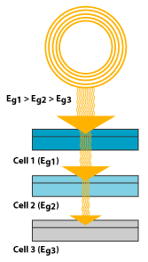
This structure, also called a cascade or tandem cell, can achieve a higher total conversion efficiency by capturing a larger portion of the solar spectrum. In the typical multijunction cell, individual cells with different bandgaps are stacked on top of one another. The individual cells are stacked in such a way that sunlight falls first on the material having the largest bandgap. Photons not absorbed in the first cell are transmitted to the second cell, which then absorbs the higher-energy portion of the remaining solar radiation while remaining transparent to the lower-energy photons. These selective absorption processes continue through to the final cell, which has the smallest bandgap.

Illustration of a multijunction device. The stack of individual single-junction cells is in descending order of bandgap (Eg). The top cell captures the high-energy photons and passes the rest of the photons on to be absorbed by lower-bandgap cells.

A multijunction device is a stack of individual single-junction cells in descending order of bandgap (Eg). The top cell captures the high-energy photons and passes the rest of the photons on to be absorbed by lower-bandgap cells.

A multijunction cell can be made in two different ways. In the mechanical stack approach, two individual solar cells are made independently, one with a high bandgap and one with a lower bandgap. Then the two cells are mechanically stacked, one on top of the other. In the monolithic approach, one complete solar cell is made first, and then the layers for the second cell are grown or deposited directly on the first.

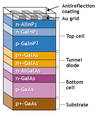
Illustration of a multijunction device, the top cell is gallium indium phosphide, next is a tunnel junction followed by a bottom cell of gallium asenide.

This multijunction device has a top cell of gallium indium phosphide, then a "tunnel junction" to allow the flow of electrons between the cells, and a bottom cell of gallium arsenide.

Much of today's research in multijunction cells focuses on gallium arsenide as one (or all) of the component cells. These cells have efficiencies of more than 35% under concentrated sunlight—which is high for PV devices. Other materials studied for multijunction devices are amorphous silicon and copper indium diselenide

http://www1.eere.energy.gov/solar/solar_cell_structures.html#pin_nip

You've probably seen calculators that have solar cells -- calculators that never need batteries, and in some cases don't even have an off button. As long as you have enough light, they seem to work forever. You may have seen larger solar panels -- on emergency road signs or call boxes, on buoys, even in parking lots to power lights. Although these larger panels aren't as common as solar powered calculators, they're out there, and not that hard to spot if you know where to look. There are solar cell arrays on satellites, where they are used to power the electrical systems

You have probably also been hearing about the "solar revolution" for the last 20  years -- the idea that one day we will all use free electricity from the sun. This is a seductive promise: On a bright, sunny day, the sun shines approximately 1,000 watts of energy per square meter of the planet's surface, and if we could collect all of that energy we could easily power our homes and offices for free.


Solar panels absorb energy to produce hydrogen at SunLine Transit Agency.

In this article, we will examine solar cells to learn how they convert the sun's energy directly into electricity. In the process, you will learn why we are getting closer to using the sun's energy on a daily basis, and why we still have more research to do before the process becomes cost effective.

Converting Photons to Electrons
The solar cells that you see on calculators and satellites are photovoltaic cells or modules (modules are simply a group of cells electrically connected and packaged in one frame). Photovoltaics, as the word implies (photo = light, voltaic = electricity), convert sunlight directly into electricity. Once used almost exclusively in space, photovoltaics are used more and more in less exotic ways. They could even power your house. How do these devices work?

Photovoltaic (PV) cells are made of special materials called semiconductors such as silicon, which is currently the most commonly used. Basically, when light strikes the cell, a certain portion of it is absorbed within the semiconductor material. This means that the energy of the absorbed light is transferred to the semiconductor. The energy knocks electrons loose, allowing them to flow freely. PV cells also all have one or more electric fields that act to force electrons freed by light absorption to flow in a certain direction. This flow of electrons is a current, and by placing metal contacts on the top and bottom of the PV cell, we can draw that current off to use externally. For example, the current can power a calculator. This current, together with the cell's voltage (which is a result of its built-in electric field or fields), defines the power (or wattage) that the solar cell can produce.

That's the basic process, but there's really much more to it. Let's take a deeper look into one example of a PV cell: the single crystal silicon cell.

Silicon
Silicon has some special chemical properties, especially in its crystalline form. An atom of silicon has 14 electrons, arranged in three different shells. The first two shells, those closest to the center, are completely full. The outer shell, however, is only half full, having only four electrons. A silicon atom will always look for ways to fill up its last shell (which would like to have eight electrons). To do this, it will share electrons with four of its neighbor silicon atoms. It's like every atom holds hands with its neighbors, except that in this case, each atom has four hands joined to four neighbors. That's what forms the crystalline structure, and that structure turns out to be important to this type of PV cell.

We've now described pure, crystalline silicon. Pure silicon is a poor conductor of electricity because none of its electrons are free to move about, as electrons are in good conductors such as copper. Instead, the electrons are all locked in the crystalline structure. The silicon in a solar cell is modified slightly so that it will work as a solar cell.

Silicon in Solar Cells
A solar cell has silicon with impurities -- other atoms mixed in with the silicon atoms, changing the way things work a bit. We usually think of impurities as something undesirable, but in our case, our cell wouldn't work without them. These impurities are actually put there on purpose. Consider silicon with an atom of phosphorous here and there, maybe one for every million silicon atoms. Phosphorous has five electrons in its outer shell, not four. It still bonds with its silicon neighbor atoms, but in a sense, the phosphorous has one electron that doesn't have anyone to hold hands with. It doesn't form part of a bond, but there is a positive proton in the phosphorous nucleus holding it in place.

When energy is added to pure silicon, for example in the form of heat, it can cause a few electrons to break free of their bonds and leave their atoms. A hole is left behind in each case. These electrons then wander randomly around the crystalline lattice looking for another hole to fall into. These electrons are called free carriers, and can carry electrical current. There are so few of them in pure silicon, however, that they aren't very useful. Our impure silicon with phosphorous atoms mixed in is a different story. It turns out that it takes a lot less energy to knock loose one of our "extra" phosphorous electrons because they aren't tied up in a bond -- their neighbors aren't holding them back. As a result, most of these electrons do break free, and we have a lot more free carriers than we would have in pure silicon. The process of adding impurities on purpose is called doping, and when doped with phosphorous, the resulting silicon is called N-type ("n" for negative) because of the prevalence of free electrons. N-type doped silicon is a much better conductor than pure silicon is.

Actually, only part of our solar cell is N-type. The other part is doped with boron, which has only three electrons in its outer shell instead of four, to become P-type silicon. Instead of having free electrons, P-type silicon ("p" for positive) has free holes. Holes really are just the absence of electrons, so they carry the opposite (positive) charge. They move around just like electrons do.

So where has all this gotten us?

N-type Plus P-type Silicon
The interesting part starts when you put N-type silicon together with P-type silicon. Remember that every PV cell has at least one electric field. Without an electric field, the cell wouldn't work, and this field forms when the N-type and P-type silicon are in contact. Suddenly, the free electrons in the N side, which have been looking all over for holes to fall into, see all the free holes on the P side, and there's a mad rush to fill them in.

Before now, our silicon was all electrically neutral. Our extra electrons were balanced out by the extra protons in the phosphorous. Our missing electrons (holes) were balanced out by the missing protons in the boron. When the holes and electrons mix at the junction between N-type and P-type silicon, however, that neutrality is disrupted. Do all the free electrons fill all the free holes? No. If they did, then the whole arrangement wouldn't be very useful. Right at the junction, however, they do mix and form a barrier, making it harder and harder for electrons on the N side to cross to the P side. Eventually, equilibrium is reached, and we have an electric field separating the two sides.


The effect of the electric field in a PV cell

This electric field acts as a diode, allowing (and even pushing) electrons to flow from the P side to the N side, but not the other way around. It's like a hill -- electrons can easily go down the hill (to the N side), but can't climb it (to the P side).

So we've got an electric field acting as a diode in which electrons can only move in one direction. Let's see what happens when light hits the cell.

When Light Hits the Cell
When light, in the form of photons, hits our solar cell, its energy frees electron-hole pairs.

Each photon with enough energy will normally free exactly one electron, and result in a free hole as well. If this happens close enough to the electric field, or if free electron and free hole happen to wander into its range of influence, the field will send the electron to the N side and the hole to the P side. This causes further disruption of electrical neutrality, and if we provide an external current path, electrons will flow through the path to their original side (the P side) to unite with holes that the electric field sent there, doing work for us along the way. The electron flow provides the current, and the cell's electric field causes a voltage. With both current and voltage, we have power, which is the product of the two.


Operation of a PV cell

How much sunlight energy does our PV cell absorb? Unfortunately, the most that our simple cell could absorb is around 25 percent, and more likely is 15 percent or less. Why so little?

Energy Loss
Why does our solar cell absorb only about 15 percents of the sunlight's energy? Visible light is only part of the electromagnetic spectrum. Electromagnetic radiation is not monochromatic -- it is made up of a range of different wavelengths, and therefore energy levels. (See How Special Relativity Works for a good discussion of the electromagnetic spectrum.)

Light can be separated into different wavelengths, and we can see them in the form of a rainbow. Since the light that hits our cell has photons of a wide range of energies, it turns out that some of them won't have enough energy to form an electron-hole pair. They'll simply pass through the cell as if it were transparent. Still other photons have too much energy. Only a certain amount of energy, measured in electron volts (eV) and defined by our cell material (about 1.1 eV for crystalline silicon), is required to knock an electron loose. We call this the band gap energy of a material. If a photon has more energy than the required amount, then the extra energy is lost (unless a photon has twice the required energy, and can create more than one electron-hole pair, but this effect is not significant). These two effects alone account for the loss of around 70 percent of the radiation energy incident on our cell.

Why can't we choose a material with a really low band gap, so we can use more of the photons? Unfortunately, our band gap also determines the strength (voltage) of our electric field, and if it's too low, then what we make up in extra current (by absorbing more photons), we lose by having a small voltage. Remember that power is voltage times current. The optimal band gap, balancing these two effects, is around 1.4 eV for a cell made from a single material.

We have other losses as well. Our electrons have to flow from one side of the cell to the other through an external circuit. We can cover the bottom with a metal, allowing for good conduction, but if we completely cover the top, then photons can't get through the opaque conductor and we lose all of our current (in some cells, transparent conductors are used on the top surface, but not in all). If we put our contacts only at the sides of our cell, then the electrons have to travel an extremely long distance (for an electron) to reach the contacts. Remember, silicon is a semiconductor -- it's not nearly as good as a metal for transporting current. Its internal resistance (called series resistance) is fairly high, and high resistance means high losses. To minimize these losses, our cell is covered by a metallic contact grid that shortens the distance that electrons have to travel while covering only a small part of the cell surface. Even so, some photons are blocked by the grid, which can't be too small or else its own resistance will be too high.

Finishing the Cell
There are a few more steps left before we can really use our cell. Silicon happens to be a very shiny material, which means that it is very reflective. Photons that are reflected can't be used by the cell. For that reason, an antireflective coating is applied to the top of the cell to reduce reflection losses to less than 5 percent.

The final step is the glass cover plate that protects the cell from the elements. PV modules are made by connecting several cells (usually 36) in series and parallel to achieve useful levels of voltage and current, and putting them in a sturdy frame complete with a glass cover and positive and negative terminals on the back.


Basic structure of a generic silicon PV cell

Single crystal silicon isn't the only material used in PV cells. Polycrystalline silicon is also used in an attempt to cut manufacturing costs, although resulting cells aren't as efficient as single crystal silicon. Amorphous silicon, which has no crystalline structure, is also used, again in an attempt to reduce production costs. Other materials used include gallium arsenide, copper indium diselenide and cadmium telluride. Since different materials have different band gaps, they seem to be "tuned" to different wavelengths, or photons of different energies. One way efficiency has been improved is to use two or more layers of different materials with different band gaps. The higher band gap material is on the surface, absorbing high-energy photons while allowing lower-energy photons to be absorbed by the lower band gap material beneath. This technique can result in much higher efficiencies. Such cells, called multi-junction cells, can have more than one electric field.

Powering a House
Now that we have our PV module, what do we do with it? What would you have to do to power your house with solar energy? Although it's not as simple as just slapping some modules on your roof, it's not extremely difficult to do, either.

First of all, not every roof has the correct orientation or angle of inclination to take advantage of the sun's energy. Non-tracking PV systems in the Northern Hemisphere should point toward true south (this is the orientation). They should be inclined at an angle equal to the area's latitude to absorb the maximum amount of energy year-round. A different orientation and/or inclination could be used if you want to maximize energy production for the morning or afternoon, and/or the summer or winter. Of course, the modules should never be shaded by nearby trees or buildings, no matter the time of day or the time of year. In a PV module, even if just one of its 36 cells is shaded, power production will be reduced by more than half.

If you have a house with an un-shaded, south-facing roof, you need to decide what size system you need. This is complicated by the facts that your electricity production depends on the weather, which is never completely predictable, and that your electricity demand will also vary. These hurdles are fairly easy to clear. Meteorological data gives average monthly sunlight levels for different geographical areas. This takes into account rainfall and cloudy days, as well as altitude, humidity, and other more subtle factors. You should design for the worst month, so that you'll have enough electricity all year. With that data, and knowing your average household demand (your utility bill conveniently lets you know how much energy you use every month), there are simple methods you can use to determine just how many PV modules you'll need. You'll also need to decide on a system voltage, which you can control by deciding how many modules to wire in series.

Obstacles
You may have already guessed a couple of problems that we'll have to solve. First, what do we do when the sun isn't shining? Certainly, no one would accept only having electricity during the day, and then only on clear days, if they have a choice. We need energy storage -- batteries. Unfortunately, batteries add a lot of cost and maintenance to the PV system. Currently, however, it's a necessity if you want to be completely independent. One way around the problem is to connect your house to the utility grid, buying power when you need it and selling to them when you produce more than you need. This way, the utility acts as a practically infinite storage system. The utility has to agree, of course, and in most cases will buy power from you at a much lower price than their own selling price. You will also need special equipment to make sure that the power you sell to your utility is synchronous with theirs -- that it shares the same sinusoidal waveform and frequency. Safety is an issue as well. The utility has to make sure that if there's a power outage in your neighborhood, your PV system won't try to feed electricity into lines that a lineman may think is dead. This is called islanding.

If you decide to use batteries, keep in mind that they will have to be maintained, and then replaced after a certain number of years. The PV modules should last 20 years or more, but batteries just don't have that kind of useful life. Batteries in PV systems can also be very dangerous because of the energy they store and the acidic electrolytes they contain, so you'll need a well-ventilated, non-metallic enclosure for them.

Deep-cycle Batteries
What kind of batteries are used in PV systems? Although several different kinds are commonly used, the one characteristic that they should all have in common is that they are deep-cycle batteries. Unlike your car battery, which is a shallow-cycle battery, deep-cycle batteries can discharge more of their stored energy while still maintaining long life. Car batteries discharge a large current for a very short time -- to start your car -- and are then immediately recharged as you drive. PV batteries generally have to discharge a smaller current for a longer period (such as all night), while being charged during the day.

The most commonly used deep-cycle batteries are lead-acid batteries (both sealed and vented) and nickel-cadmium batteries. Nickel-cadmium batteries are more expensive, but last longer and can be discharged more completely without harm. Even deep-cycle lead-acid batteries can't be discharged 100 percent without seriously shortening battery life, and generally, PV systems are designed to discharge lead-acid batteries no more than 40 percent or 50 percent.

Also, the use of batteries requires the installation of another component called a charge controller. Batteries last a lot longer if care is taken so that they aren't overcharged or drained too much. That's what a charge controller does. Once the batteries are fully charged, the charge controller doesn't let current from the PV modules continue to flow into them. Similarly, once the batteries have been drained to a certain predetermined level, controlled by measuring battery voltage, many charge controllers will not allow more current to be drained from the batteries until they have been recharged. The use of a charge controller is essential for long battery life.

DC to AC
The other problem is that the electricity generated by your PV modules, and extracted from your batteries if you choose to use them, is direct current, while the electricity supplied by your utility (and the kind that every appliance in your house uses) is alternating current. You will need an inverter, a device that converts DC to AC. Most large inverters will also allow you to automatically control how your system works. Some PV modules, called AC modules, actually have an inverter already built into each module, eliminating the need for a large, central inverter, and simplifying wiring issues.


General schematic of a residential PV system with battery storage

Throw in the mounting hardware, wiring, junction boxes, grounding equipment, overcurrent protection, DC and AC disconnects and other accessories and you have yourself a system. Electrical codes must be followed (there's a section in the National Electrical Code just for PV), and it's highly recommended that the installation be done by a licensed electrician who has experience with PV systems. Once installed, a PV system requires very little maintenance (especially if no batteries are used), and will provide electricity cleanly and quietly for 20 years or more.

If photovoltaics are such a wonderful source of free energy, then why doesn't the whole world run on solar power? Some people have a flawed concept of solar energy. While it's true that sunlight is free, the electricity generated by PV systems is not. As you can see from our discussion of a household PV system, quite a bit of hardware is needed. Currently, an installed PV system will cost somewhere around $9 per peak Watt. To give you an idea of how much a house system would cost, let's consider the solar energy -- a model residential home in Raleigh, North Carolina, with a PV system set up by the North Carolina Solar Center to demonstrate the technology. It's a fairly small home, and it is estimated that its 3.6-kW PV system covers about half of the total electricity needs (this system doesn't use batteries -- it's connected to the grid). Even so, at $9 per Watt, this installed system would cost you around $32,000.

That's why PV is usually used in remote areas, far from a conventional source of electricity. Right now, it simply can't compete with the utilities. Costs are coming down as research is being done, however. Researchers are confident that PV will one day be cost effective in urban areas as well as remote ones. Part of the problem is that manufacturing needs to be done on a large scale to reduce costs as much as possible. That kind of demand for PV, however, won't exist until prices fall to competitive levels. It's a Catch-22 situation. Even so, demand and module efficiencies are constantly rising, prices are falling, and the world is becoming increasingly aware of environmental concerns associated with conventional power sources, making photovoltaics a technology with a bright future

http://www.thesolarplan.com/articles/how-do-solar-panels-work.html

انرژی زیست توده

زيست توده ترجمه لغت انگليسي بيوماس(Biomass ) مي­باشد براي زيست توده تعاريف مختلف و متنوعي در جهان مطرح مي­باشد. بعنوان يك تعريف ساده ميتوان گفت:
زيست توده شامل كليه موادي در طبيعت ميشود كه در گذشته نزديك جاندار بوده، از موجودات زنده بعمل آمده و يا زائدات و ضايعات آنها ميباشند.
ميدانيم كه منشاء منابع فسيلي نيز منابع زيست توده ميباشد ولي تفاوت آنها در اين است كه منابع فسيلي از منابع زيست توده كه در گذشته بسيار دور زنده بودند و تحت شرايط فشار و دماي خاص حاصل شده­اند(دهها ميليون سال پيش).
اتحاديه اروپا مطابق ابلاغيه 2000/177/EC جهت توسعه استفاده از زيست توده در توليد برق در بازار داخلي اروپا تعريف زيست توده را به شكل زير مطرح نمود:
زيست توده كليه اجزاء قابل تجزيه زيستي از محصولات، فاضلابها و زايدات كشاورزي (شامل مواد گياهي و حيواني)، صنايع جنگلي و ساير صنايع مرتبط، فاضلابها و زباله­هاي تجريه­پذير زيستي شهري و صنعتي ميباشد.
 
تاريخچه بهره برداري زيست توده :
از نقطه نظر تاريخي استفاده از انرژي زيست توده به ابتدايي ترين دوره هاي تاريخ باز مي‌گردد از زماني كه آتش شناخته شد، انسان نخستين همواره چوب و برگ خشك درختان را به عنوان سوخت استفاده مي‌كرده و اين چرخه تا قرن حاضر نيز ادامه پيدا كرده است.
در خصوص بيوگاز، قديمي ترين مورد خروج گاز و اشتعال ناقص آن به وسيلة دفن زباله در طبقات زيرين زمين توسط پيلي ني روس گزارش شده است. وي خروج گاه به گاه گاز طبيعي و اشتعال ناقص آن را از طبقات زيرين زمين مشاهده كرد ولي وان هلمونت درسال 1630 شناسائي و اشتعال اين گاز را رسماً اعلام كرد. در ايران نيز استفاده از بيوگاز سابقه اي قابل توجه دارد. محمدبن حسين عاملي معروف به شيخ بهائي (1031-935 ه ق ) نخستين كسي است كه بر اساس منابع تاريخي اين منبع انرژي را به عنوان سوخت يك حمام در اصفهان به كار برده است.
اولين هاضم توليد گاز متان در ايران در روستاي نياز آباد لرستان در سال 1354 ساخته شده است. اين دستگاه به گنجايش 5 متر مكعب فضولات گاوي روستا را مورد استفاده قرار داده و بيوگاز مصرفي حمام مجاور را تأمين مي نمود.
 
وضعيت فعلي بهره برداري از زيست توده در جهان :
امروزه منابع مفيد و كاربردي زيست توده تنها به چوب و برگ خشك محدود نمي شود و طيف وسيعي از مواد از جمله پسماندهاي جامد و مايع شهري و پسماندهاي صنعتي و غيره را نيز در بر ميگيرد.
منابع انرژي تجديد پذير پس از ذغال سنگ، نفت و گاز طبيعي، چهارمين منبع بزرگ انرژي در دنيا مي‌باشند. اين منبع حدود 14 درصد از انرژي اوليه جهان را تامين مي‌نمايد و در حال حاضر بيش از 5/11% از انرژي اوليه جهان توسط منابع زيست توده تامين مي­گردد. و اين در حالي است كه در ايالات متحده آمريكا 3-4 درصد از انرژي اوليه مورد نياز فقط از منابع زيست توده تامين ميشود. قابليتهاي زيست توده تنها در توليد حرارت نيست، بلكه در توليد سرما، سوختهاي مورد نياز براي حمل و نقل و توليد انرژي الكتريكي نيز استفاده دارد. در سال 2005حدود 44000 مگاوات نيروگاه توليد برق ( با انواع فن آوريها ) و 225000 مگاوات حرارتي نيروگاه مدرن توليد حرارت با منبع زيست توده احداث شده است كه حدود 10000 مگاوات آن فقط در ايالات متحده بوده است (حدود 58 درصد از بازار توليد انرژي از منابع تجديد پذير در امريكا). همچنين بيش از 50 ميليارد ليتر سوخت تجديدپذير از منابع زيست توده توليد و مصرف مي­گردد.
برمبناي مطالعات انجام شده، منابع زيست توده حدود 64 درصد از منابع اوليه انرژيهاي نو در اتحاديه اروپا را به خود اختصاص داده است و حدود 9 درصد از انرژي الكتريكي توليدي و 98 درصد از انرژي حرارتي توليدي از طريق منابع انرژيهاي نو به منابع انرژي زيست توده تعلق دارد. ( با در نظر گرفتن منابع برق آبي).
انرژي زيست توده تنها منبع انرژي تجديدپذير مي­باشد كه انرژي را بفرم­هاي برق، حرارت، سرما و سوخت خودرو و به اشكال جامد، مايع و گاز تحويل مي نمايد. بعلاوه مواد زيستي جايگزين خوراك پتروشيمي و ... نيز از محصولات ديگر آن مي­باشد.
منبع: سازمان انرژیهای نو ایران(سانا)

Self-Assembling Solar Cells

Self-Assembling Solar Cells What can a scientist do with salad dressing apart from telling you that it increases the taste of salad manifold? But that’s the beauty of this profession. As Newton could give some theories when he saw an apple falling from a tree, salad dressing can inspire scientists towards a brand new type of solar cells. The researchers managed to create a cheap, efficient and very simple method of making solar cells. The USP of these solar cells is that they self-assemble on a variety of substrates. The new technique draws parallel from the fact that oil and water don’t mix at all. Another unique fact is forces the elements of electronic components for example solar cells assemble themselves at the boundaries between the two types of liquids. This work was recently published in Proceedings of the National Academy of Sciences (PNAS).

University of Minnesota researchers used a number of other methods to create solar cells. It is believed that the technology can be used on commercial scale too. This method has one more benefit that it can force components to self-assemble onto a range of substrates, and not just a select, expensive few.

Till now scientists are applying the use of gravity on such mechanisms. Many lines are engraved on a substrate that was put inside a liquid. Now various electronic components settle down at designed locations. But such methods have their own limitations. They face problems like low yields, and low concentration. Therefore commercial application of such a mechanism was almost impossible. UM expert Heiko Jacobs, the leader of the research team, expresses his opinion, “That’s what we tried for at least two years and we were never able to assemble these components with high yield – gravity wasn’t working.”

He explained his innovative approach further, “Then we thought if we could concentrate them into a two-dimensional sheet and then have some kind of conveyor belt-like system we could assemble them with high yields and high speed.”

The researchers constructed a system at the boundary between water and oil. The substrate is dipped into the liquid, and then gently pulled out. Small components settle down into place, and the method is enormously effectual. The research team was successful to fit about 64,000 elements on a substrate in less than three minutes.

University of Washington in Seattle Nanoengineering Professor Babak Parviz explains, this work is a “clear demonstration that self-assembly is applicable across size scales. Self-assembly is probably the best method for integrating high-performance materials onto unconventional substrates.” Currently the UM team is trying to find out the minimum and maximum sizes that can be produced for electronic components. In short, we can say that the technology could transform the solar cell industry in that it allows for the large-scale assembly of high-quality electronic components.

The technology can be utilized for the highly efficient solar cells that can be built quickly and cheaply on various materials.

http://www.alternative-energy-news.info